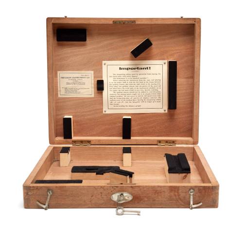
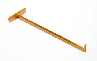
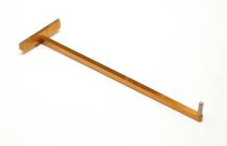
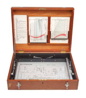
Box for Mechanical integrator
Object numberV00055653
NameBox
Mediummetal, wood
DimensionsOverall (closed box, full): 80 × 367 × 301 mm, 4200 g
Overall (open box): 350 mm
Overall (open box): 350 mm
ClassificationsTools and equipment
Credit LineGift from University of New South Wales Naval Architecture Stream
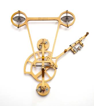
DescriptionThe mechanical integrator is an elegant and practical mathematical device created in the mid-1800s. It was primarily used in naval architecture for complex stability calculations. It is related to the planimeter which is widely used in a number of professions to measure areas from a scale plan, in particular areas whose boundary or perimeter is not geometrically uniform. The mechanical integrator’s invention in the 1850s matched a time when the design, drafting and construction of vessels was becoming much more accurate and precise, and could finally benefit from a full study of its stability over the a range of 180 degrees heel and different displacement conditions, including light (IE empty) ship, full load and one or two partial loadings in between.
For over two centuries many vessels had been built from plans, or ‘draughts’ as they were often known, but the main use of these plans was to help the economical ordering and cutting of timbers for the various parts of the of the vessel. At the same time, craft were not built closely enough to the plan to provide an accurate answer to any calculations made from the plan. However, a very significant factor to be considered was that although it was known how to use a plan for a stability calculation, it took days by a highly trained and therefore expensive draftsman to calculate the stability for just one angle of heel in one loading condition. A range was needed to graph the outcome, and it took considerably more resources and cost than was available, and at that time may still not have yielded a useful answer.
The advent of steam powered, iron vessels, built closely to their drawings began to improve one of these factors, but accidents that were subsequently attributed to poor stability began to drive the need for a means of calculating stability.
The Amsler integrator solved the problem of measuring the factors needed from the plan and then undertaking the calculation efficiently and in a reasonable timespan, so that it was feasible to do a calculation at intervals of heel and graph the resulting stability curve for each load condition. What was needed was a means of measuring from the body plan of the hull the heeled immersed area of each hull section, locating the centre of this area, and then combing these individual answers to provide an overall result for the heeled vessel.
The integrator combined a planimeter function to measure the immersed areas of the hull cross sections on the vessel’s body plan, but it also located the centre of each area relative to the axis of the integrator’s framework. The distance from the axis of this centre squared, multiplied by the area (also a square function) gives an answer that is in units to the 4th power. i.e.: d squared x area = units to 4th power - and is known as the 2nd Moment of Area. By creating a table of results for each section, simple maths using additions, multiplication and division will provide the required answer.
The eventual answer is the heeled centre of buoyancy for the hull, vital for calculating a ships stability at varying angles of heel. A curve for stability can be established, an easily understood example is the GZ curve, being the horizontal distance between the ships Centre of Gravity and Centre of Buoyancy, in other words the righting lever.
Naval Architecture and calculations and stability reports also include the metacentric height as a measure of stability. The metacentre is the point on the heeled centreline vertically above the centre of buoyancy. This height becomes a further indicator of a ship’s stability behaviour in regards to being resistant to or easy to roll, and where a higher metacentre gives stronger or stiffer rolling behaviour. In this regard, it is more descriptive than a GZ curve of the righting lever.
HistoryThe four objects acquired from the University of NSW Naval Architecture Stream represent items used in the classical period of naval architecture and engineering, when calculations were done by hand and practical methods were used for testing, in contrast to the contemporary use of computers for design, drafting, calculation and testing.
The mechanical integrator and Ralston ship’s stability and trim indicator were used for teaching purposes from the 1950s until the 1990s when computer-based methods became fully accepted in the profession and for teaching purposes. The test tank models were acquired by the NSW University when the towing tank facility that was at Sydney University was closed in the late 1970s.
The items have remained with the NSW University until the Naval Architecture stream was discontinued at the end of 2018, and then donated to the museum for the collection.
SignificanceThese are excellent examples of objects that interpret the story of classical and practical naval architecture with a strong provenance and connection to Australian vessel design and study. They come from the University of NSW Naval Architecture Stream and demonstrate classical methods of engineering and naval architecture using hand calculations and practical models testing to develop and assess a ship’s design and subsequent operation.
The mechanical integrator is an excellent example of a specific instrument designed to enable difficult and tedious calculations relating to a vessel’s stability to be made in a relatively short time. It did not require a highly skilled person to operate.


18th century