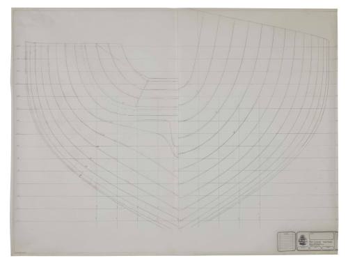
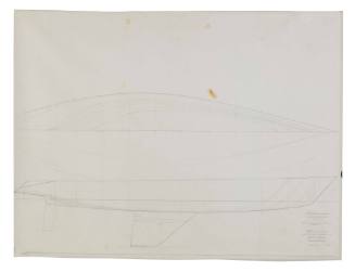
Hull lines drawing
Designer
Ben Lexcen
(1936 - 1988)
Datec 1985
Object numberANMS1543[020]
NamePlan
Mediumink on drafting film
Dimensions0
Copyright© Ben Lexcen
ClassificationsMaps, charts and plans
Credit LineAustralian National Maritime Museum Collection
DescriptionA Ben Lexcen working hull lines-plan, for an unknown yacht from circa 1984.
HistoryHull shape: Prior to the twentieth century, wooden half or full hull models of ships and boats were constructed by shipwrights as a means of planning a ship's design and sheer, ensuring the ship would be an exact scale replica of the actual ship's hull. They were made to show the customer or owner the form which the finished hull would take and could be altered if the customer thought something not quite as he wanted. The model of the vessel was then measured and ‘lofted’ (drawn) full size on the workshop floor. During lofting, any errors made in measuring were corrected as the hull lines were drawn using long wooden battens temporarily nailed to the workshop flow drawing. With the ‘three-dimensional plan’ drawn and checked, wooden templates of each part were ‘lifted off’ ready to cut the wood or steel parts, such as keel, deadwood, stems and hull frames. Some half models for steel ships, indicate the size and shape of each of the steel plates on the hull. With the advent of computer aided design (CAD), half models are now mostly built as decorative nautical-art, invariably constructed after a ship, boat or yacht has been built.
The Lines Plan:
The scientific ‘lines-plan’, doubtless evolved from the lofting process, as it became clear a three-dimensional-drawing, made to a scale, could be used easier and more accurate than a hand carved model. Based on the information from the client, noted in the technical specification, the naval architect will produce a lines-plan and a general arrangement plan. The lines-plan allows the naval architect to calculate the weight (displacement) of the vessel, centre of gravity and show where and how it will float. It gives precise information on the area of the hull above and below the waterline so the amount of building materials can be calculated. It allows calculations to be made for the type and size of engine or sail area, size of propellers and amount of cargo or passengers the vessel can safely carry. Generally, the calculations a naval architect will make from the lines-plan will be: The Weight (Displacement) Calculation, Longitudinal Centre of buoyancy (LCB), Longitudinal centre of gravity (LCG), Vertical Centre of gravity (VCG), Metacentric Height (KM), Hull Expansion design drawing, Hull Surface Area (HSA), Wetted Surface (WS), Weights & Moments Estimate, Stability Booklet, Prismatic Coefficient (PC), Sail centre of effort (C of E), Table of Offsets.SignificanceRegardless if designing a yacht, fishing boat or an oil tanker, the ‘hull lines plan’ is the start of the project, and where the naval architect uses all his skill and experience, plus a good deal of passion, to produce a hull shape which best suits the vessels intended use. This is why a naval architect often feels a special relationship with the ‘lines-plan drawing’, and is reluctant to share or give away any of the contents


